AutoCAD® 2000
Unleashing the Power of Plotting
Introduction
AutoCAD 2000 delivers significant plotting feature enhancements that enable you to plot presentation quality drawings faster, easier, and with more consistency than ever before. Paper space drawing layouts are now integrated with the plotting process taking the guesswork out of plotting your drawings, by providing you with an accurate paper-based visual representation of your drawing before it is plotted. The new Plot dialog UI is designed to provide power users with all the control they need, and provide casual users with an easier way to plot. New wizards make it easier to setup Plot Device Configurations, Plot Style Tables (formally Pen Assignments), and Paper space Layouts. Together these new features will enhance your productivity and provide you with consistent high quality plotting output. This paper is intended to introduce some new plotting concepts, step you through plotting an R14 drawing, and then answer some questions that we anticipate you may have. You should also refer to the AutoCAD 2000 online help and User’s Guide for more information on Plotting and Layouts.
Concepts
There are a few new concepts that you should familiarize yourself with before you start plotting.
Paper space Layouts
A paper space layout is used to compose or layout your model drawing for plotting. A layout may consist of a title block, one or more viewports, and annotations. Layouts use plot settings and plot style tables to create a visual representation of a paper drawing. The paper representation takes into account the plot device, paper size, paper orientation, printable area, scale, plotting area, lineweights, color screening, grayscale, dithering, linetypes, end and joint styles, and fill patterns. With paper space layouts you can see exactly how you drawing will plot before you plot it.
Plot Settings are Saved in Paperspace Layouts and Model space
Model space and layouts store the plot settings you specify after each plot. If you plot the same drawing using different scales or different lineweights, you can create multiple layouts and store different plotting settings in each layout. Alternatively, you can create a page setup for each plot. Page setups store your plot settings and can be easily loaded at plot time. The Page Setup dialog box can be used to enter plot settings without plotting your drawing.
Plot style Tables (Pen Assignments)
In Release 14, pen assignments and color were combined to determine the visual characteristics of a drawing when plotted. In AutoCAD 2000, plot style tables are combined with color to determine the visual characteristics of a drawing when plotted. A plot style table is a device independent file that controls lineweights, color screening, grayscale, dithering, linetypes, end and joint styles, fill patterns, and pen numbers at plot time. You can create several plot style tables and assign the desired table at plot time.
Configuring a Plot Device
AutoCAD 2000’s new Plotter Manager enables you to configure and manage plotter configurations. From the Plotter Manager, you can choose the Add a Plotter wizard to step through the process of configuring a plot device and then create a plotter configuration file (.pc3) that stores plotter settings. A plotter configuration file is used to setup the plotter at plot time The Plotter Configuration Editor, modifies existing plotter configuration files.
You can create a plotter configuration file for AutoCAD 2000 New HDI printer drivers, a network printer, or a Windows system printer. A plotter configuration file controls media type, media source, default paper size, plot resolution, color depth, plot raster quality etc. These settings are sent to the plot device at plot time to ensure that the plotter is properly setup for your plot.
Setup Windows System Printers
Plotter configuration files can be created for your Windows system printers, enabling you to setup your plotter differently for AutoCAD without affecting other Windows based applications that use the same printer.
Sharing Plotter Configuration files.
Plotter configuration files can be easily distributed and shared on a network. You can configure all of your plotters once, store the plotter configuration files in a common network location, then configure AutoCAD’s Printer Configuration Search Path to search the network directory where your plot configuration files are stored. In this manner, all your AutoCAD stations can share the same plotter configurations.
Please consult the AutoCAD 2000 documentation for further concepts and information about paper space layouts and plotting.
Components of plotting
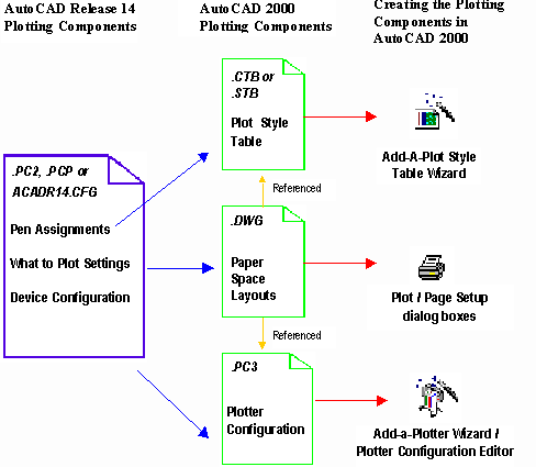
AutoCAD Release 14 divides plotting into three major components, pen assignments, plot device and what to plot settings. AutoCAD 2000 utilizes the same components, but they are created and managed differently. The diagram in figure 1 illustrates how these components relate to Release 14 and how they are created in AutoCAD 2000. As you read about some of the new plotting procedures that are discussed throughout this document, you may want to consult the diagram in figure 1.

Plotting for the first time
Let’s step through plotting a drawing in AutoCAD 2000, and then answers some questions that we anticipate you may have. We will concentrate on the basics for now. Let’s say you’ve just installed AutoCAD 2000 and you want to plot a drawing that was created in R14. This is how to plot in the drawing in AutoCAD 2000:
- After installing AutoCAD 2000, open an R14 drawing, then from the File menu choose Plot.
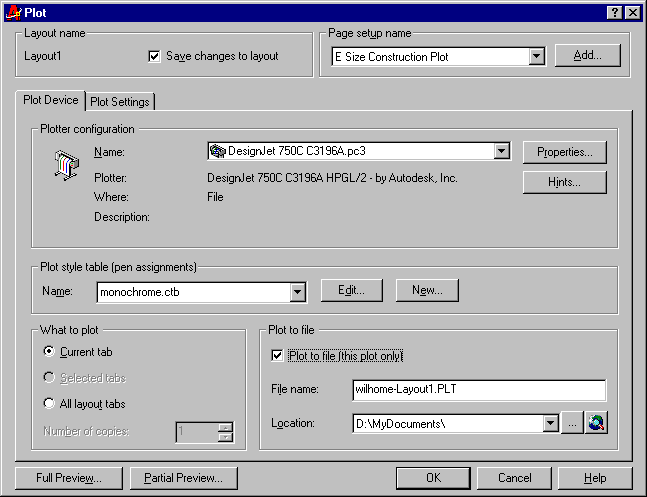
- In the Plot dialog box, on the Plot Device tab, under Plotter Configuration, select a plotting device.
- Under Plot style table (pen assignments), select the plot style table you want to attach to the current drawing.
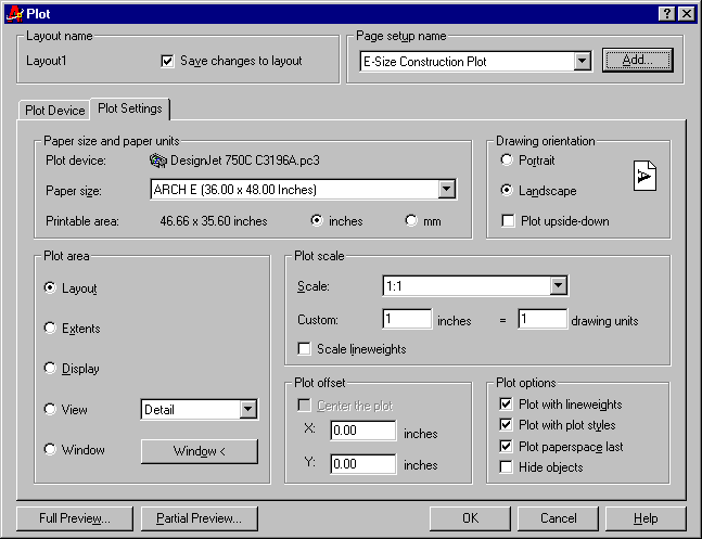
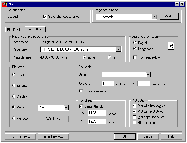
- On the Plot Settings tab, specify the following settings:
NOTE: If, during AutoCAD 2000 installation, you chose to migrate your R14 pen settings, when you select the plot style table list, a list of plot style tables will be available with the names of the plotters you configured in R14. Plot style tables are automatically created for devices for which you used pen assignments in R14. You will also see plot style tables named ACAD2000 and MONOCHROME.
If you did not migrate your R14 pen settings during the AutoCAD 2000 installation,
as you select the plot style table list, you will see ACAD2000 and MONOCHROME.
- Paper Size
- Drawing Orientation
- Plot Area
- Plot Scale
- Plot Offset
- To verify that your plot fits on the specified paper size, choose Partial preview. (Optional)
- To plot your drawing choose OK.
To preview your drawing with lineweights and plot styles (pen assignments) applied, choose Full Preview. (Optional)
AutoCAD 2000 New Plot dialog

Figure 2 Plot dialog - Plot Device tab


Figure 3 Plot dialog - Plot Settings tab
Questions and Answers
What happens when I plot this drawing again?
All plot settings you specify are now automatically saved in the drawing and applied at plot time. By choosing Plot, then choosing OK, the drawing will plot using its last plot settings.
When you plot your drawing from model space, the plot settings are saved in model space. When you plot your drawing from a layout, the plot settings are saved in the layout. You can store different plot settings in the drawing for the model tab and for each of the layout tabs.
Layouts use plot settings and plot style tables to create a visual representation of a paper drawing. The paper representation takes into account the plot device, paper size, paper orientation, printable area, plot scale, plotting area, lineweights, color screening, grayscale, dithering, linetypes, end and joint styles, and fill patterns. With paper space layouts you can see exactly how your drawing will plot before you plot it
NOTE: Plot style table files and plotter configuration files are stored separately from the drawing, and are referenced at plot time. Please see below for a definition of a plot style table and plotter configuration file.
What if I do not want to save my plot settings in the drawing?
In the Plot dialog box, uncheck Save Changes to Layout at the top of the Plot dialog box.
Where did my R14 pen assignments come from?
As part of the AutoCAD 2000 installation, your acadr14.cfg file was analyzed and the pen assignments for your R14 plot devices were converted to color-dependent and named plot style
tables. A color-dependent plot style table is a file that defines how the objects in your drawing will be plotted based on their AutoCAD color. Named plot style tables will be discussed in a later question. A plot style table file is stored independent of a plotter configuration file and can be used with any plot device.How do I change my lineweight settings in a color-dependent plot style table?
In the Plot dialog box, beside the Plot Style Table, drop down list there are two buttons, Edit and New.
- Choose Edit to modify the lineweight settings for an existing color-dependent plot style table.
- Choose New to either create a new color-dependent plot style table from scratch, from a PCP, PC2, or from an acadr14.cfg file. Once the new plot style table is created, you canchoose Edit to modify lineweight settings.
What other plot characteristics can I set in a color-dependent plot style table?
You can set the following plotting characteristics:
- Plotted color (including dithering and gray scale)
- Pen # (for pen plotters)
- Virtual pen # (optionally sets the pen # to use for non pen base devices, such as HP DesignJets)
- Screening Value
- Linetype
- Lineweight
- End and Join style
- Fill Pattern (for objects with solid fill, or polylines with width)
Can I use all these plot characteristics on any device?
Yes, you can create a color-dependent plot style table with any of the above plotting characteristics and use it with any plotting device. If the plotting device you use is not capable of interpreting some of the plot style values, those values will be ignored.
EXAMPLE: Pen plotters cannot use a screening value, so the screening value will be ignored when plotting to a pen plotter.
Where did the list of paper sizes in the "Plot settings" tab come from?
The paper size list consists of dimensionally accurate paper sizes that are supported by the device you selected. The list is based on actual paper dimensions and the orientation of the paper when it is loaded into the plot device.
EXAMPLE: If you have a plotter with a 24" wide bed, the maximum paper width in the list will be 24". Therefore, you would see a listing for 24"x36" but not 36"x24" since a 36" wide piece of paper does not fit in a 24" wide plotter.
How does AutoCAD know what the printable area is for each paper size?
The printable area is based on the device and paper size that you have selected. You no longer need to create user paper
sizes to get the maximum printable area for standard paper sizes that your plotter supports.What if the paper size I want is not listed.
To create custom paper sizes, use the plotter configuration editor:
- From the AutoCAD 2000 File menu, choose Plotter Manager.
- In the Plotter Manager, double-click on the plotter configuration file for your plotting device (device name. pc3)
- In the Plotter Configuration Editor, on the Device and Document Settings tab, under the Calibration & User Defined Paper Sizes leaf, choose Custom Paper Sizes.
- Choose Add, then use the Custom Paper Size wizard to define a custom paper size. To modify existing custom paper sizes, choose the custom paper size, then choose Edit.
- To modify a standard paper size, choose Modify Standard Paper Sizes, then select the paper size you want to modify and choose Modify. A wizard steps you through modifying the unprintable area and paper source.
NOTE: Prior to creating or modifying paper sizes, you must have configured a plotting device. To configure a plotting device, from the File menu choose Plotter Manager, then select the Add a Plotter wizard. A plotter configuration file is created that can be modified or copied at any time. When you configure a device using the Add a Plotter wizard, you can choose Edit Plotter Configuration on the Finish page to launch the Plotter Configuration Editor. A custom paper size can be then added by following the steps specified above.
To modify a standard paper size or add a custom paper size to a Windows system printer, you must first add the system printer to AutoCAD using the Add a Plotter wizard. You can then modify the unprintable area of a paper size or create a custom paper size using the Plotter Configuration Editor.
Why did Autodesk start using plotter configuration files?
Recently, many new capabilities have been added to plotters. Features such as color depth, media type, raster and vector print quality, media source and merge controls are common on many devices. Customers have requested a method of configuring these settings at plot time and then storing the settings for re-use. A plotter configuration file provides you with the method to store and use plotter settings. You can configure multiple configuration files for the same plot device, then simply by choosing a different plot device from the Plot dialog you have selected a different configuration.
Sharing Plotter Configuration files.
Plotter configuration files can also be easily distributed and shared on a network. You can configure all of your plotters once, store the plotter configuration files in a common network location, then configure AutoCAD’s Printer Configuration Search Path to search the network directory where your plot configuration files are stored. In this manner, all your AutoCAD stations will share the same plotter configurations.
I thought one of the new features for AutoCAD 2000 was using color for color when plotting?
AutoCAD 2000 is configured by default to use color to determine how a drawings will plot. If you would like to use color for color, select Options from the Tools menu, then on the Plotting tab, select Default Plot Style Behavior, and then choose Use Named Plot Styles. You can also designate the plot style table you would like to attach to all new and pre-AutoCAD 2000 drawings when they are opened for the first time.
NOTE: During AutoCAD 2000 installation, your R14 pen assignments are converted to named plot style tables. If one of these tables is attached when a pre-AutoCAD 2000 drawing is first opened, AutoCAD will assign the plot styles from the table to the layers and objects in the drawing. The plot styles will be assigned based on the color of objects and layers in the drawing.
The default plot style names in named plot style tables are Style 1, Style 2, Style 3, etc. If you want to change the names to something more meaningful (i.e. electrical, plumbing, walls, etc.), we recommend that you change the plot style names before you use them to open a pre-AutoCAD 2000 drawing. If you modify the names of plot styles in the plot style table after the plot styles have been applied, the plot style names in the drawing will not match the names in the plot style table.
What’s the difference between a named plot style table and a color-dependent plot style table?
A color-dependent plot style table determines how your drawing objects will plot based on color. This table contains a list of 255 colors. You assign plot characteristics to each color in the table to determine how your drawing will plot. This is very similar to the way R14 pen assignments work today.
A named plot style table does not depend on color. Instead, it has a list of names that you define. For each name you create, you assign plotting characteristics. The name is referred to as a plot style, the table is referred to as a named plot style table. In your drawing, you apply the plot styles to layers and objects to determine how they will plot. A named plot style is assigned independent of color, which means that objects with the same colors can be plotted differently.
How do I edit or create a new named plot style table?
- From the File menu, choose Plot.
- In the Plot dialog box, choose Edit to modify an existing plot style table.
- Choose New to either create a new table from scratch, from a PCP, PC2, or from an acadr14.cfg file.
What is the next step after I have created a named plot style table?
Once you’ve created a named plot style table, you can attach it to your drawing and assign the plot styles it contains to the layers and objects in your drawing. A plot style table can be attached using the Plotstyle dialog box. Plot styles can then be assigned to layers using the Layer Properties Manager, and to objects using the Properties window or the Properties toolbar. (see table for more options)
Methods used to attach plot style tables and assign plot styles.
| Attach a Plot Table | Assign a plot style to a layer | Assign a plot style to an object | Set the running plot style |
| Plotstyle Dialog box | Layer Properties Manager | Properties window (when an object is selected) | Properties window (when no objects are selected) |
| Object Properties Toolbar (select Other… in plot style drop down) | -layer | Object Properties Toolbar (when an object is selected) | Object Properties Toolbar (when no objects are selected) |
| Properties window (when no objects are selected) | Plotstyle | Plotstyle | |
| Plot Dialog box | Chprop | -Plotstyle | |
| Page Setup Dialog | Change |
What do I need to do if I have been using color-dependent plot style tables and I now want to use named plot style tables?
AutoCAD provides a wizard that steps you through the process of converting the color-dependent plot style table that you’ve attached to your drawing to a named plot style table. After converting the color-dependent plot style table to a named plot style table, the wizard attaches the new named plot style table to your drawing for future use. When this drawing is opened again, AutoCAD assigns plot styles from the newly created named plot style table to layers and objects in your drawing based on their AutoCAD color.
Summary
- Paper space layouts give you a WYSIWYG preview of you drawing before it plots.
- A new plot dialog provides all the power an experienced user needs, and enables a simpler path for casual users.
- Plot settings are now saved in your drawing providing consistent plotting output.
- Plot style tables enable you to create high quality presentation drawings.
- AutoCAD 2000’s Plot Style Table Editor makes it easy to setup presentation quality plotting standards.
- Device accurate paper sizes take the guesswork out of plotting to a different plot device, by ensuring that your drawings do not get clipped.
- Plotter configuration files ensure that your plot device settings are exactly what you need every time you plot. Multiple plotter configurations files each with different plotter settings, can be created for the same device.
- Save time by configuring your plotters once, and then share or copy your plotter configuration files to all the AutoCAD stations on your network.
- Unleash the power and flexibility of Named Plot Style tables to further enhance your plotting capabilities.
